The Welding of Offshore Wind Monopiles
In part one of this series, we provided a background of the offshore wind industry. In this article, we will elaborate on the welding of offshore wind monopiles.
Typical Fabrication Process of Offshore Wind Monopiles
To enable the use of large turbines in deeper waters and harsher environments, offshore wind monopiles have grown larger in size over the years. A typical monopile design has a bottom diameter of between 6 to 12 meters, lengths of up to 120 meters, and wall thicknesses of up to 150 millimeters.
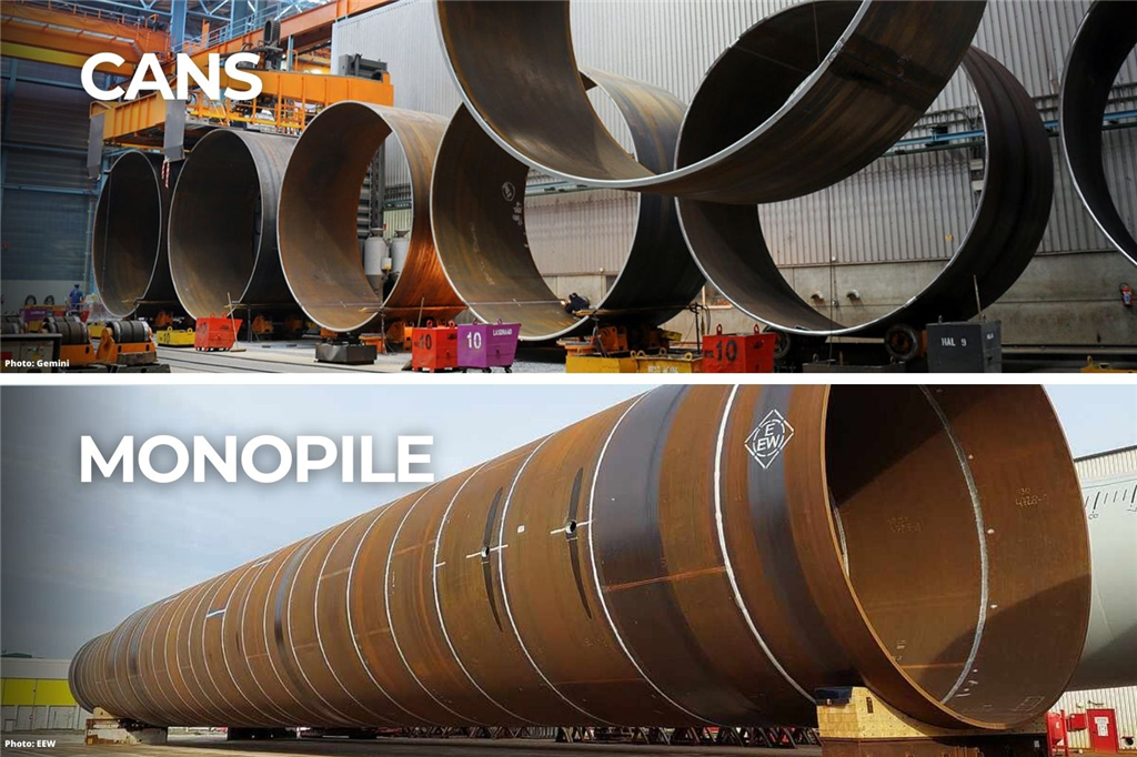
Large steel plates (typically S355 grade or equivalent) are rolled into a cylindrical or conical shape using specialized bending machines. The joint is tack welded and preheated to 80–150oC. Once the preheat temperature is reached, the process to weld the longitudinal seam begins. The Submerged Arc Welding (SAW) process is employed because welding takes place in the flat position and high deposition rates are required to fill up the thick joints. These individually rolled and welded cylindrical or conical pieces are known as “cans”. The cans are subsequently placed side-by-side in what is commonly referred to as a “growing line”. The weld joints are tacked, preheated, and SAW is used to perform circumferential welding. After the monopile is fabricated, it undergoes surface treatment and is transported to the offshore wind farm site for installation.
Typical Welding Challenges when Fabricating Offshore Wind Monopiles
Meeting Welding Productivity Goals
Due to the sheer size of the monopiles, the main challenge that most fabricators will face is achieving the welding productivity goals so that project timelines can be met. Here are five factors to consider when attempting to improve welding throughput.
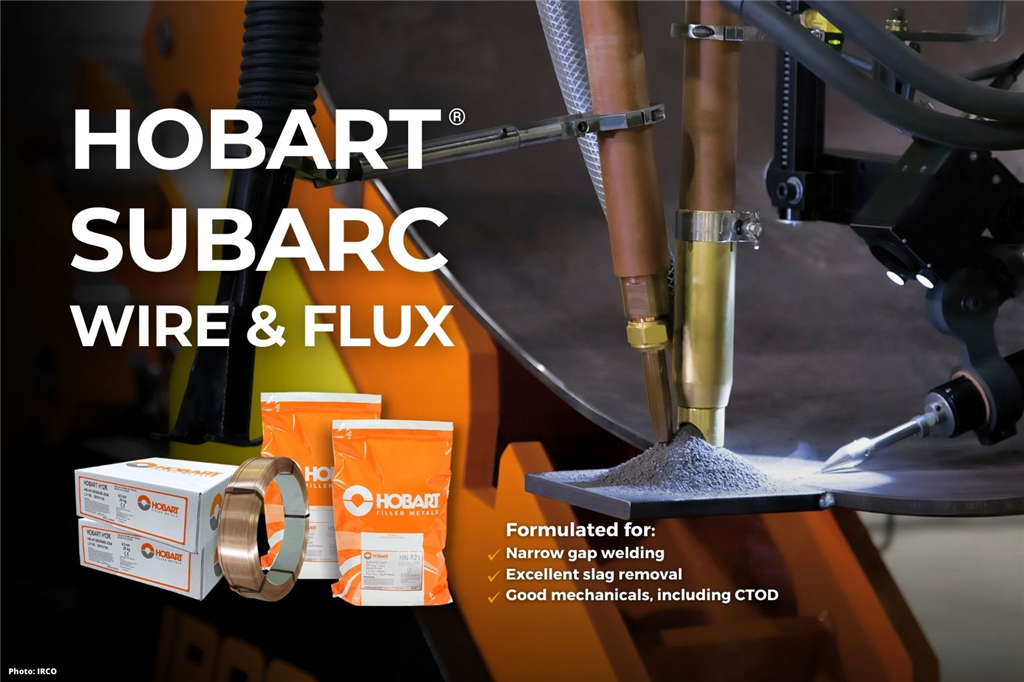
1. Joint Configuration. A change in joint configuration can reduce the welding time during production. For example, a double-V butt joint with a 60o included angle may take 10t hours to complete with the SAW process. By changing the included angle to 50o, the same joint can be completed in 8t hours, a 20% reduction. Fabricators can further reduce the welding time significantly by switching to narrow groove welding, which typically consists of a U-groove with 20o included angle and R8 radius. Fabricators will need to invest in a milling machine to achieve the necessary narrow groove joint preparation. It is important to note that as the included angle is reduced, not all SAW fluxes will offer good slag release. Good slag release is important as it helps to prevent slag inclusion and assist welders to focus on welding, instead of grinding and chipping slag. Our Hobart® HN-521 and Hobart® HN-528 fluxes are specially designed for narrow groove welding.
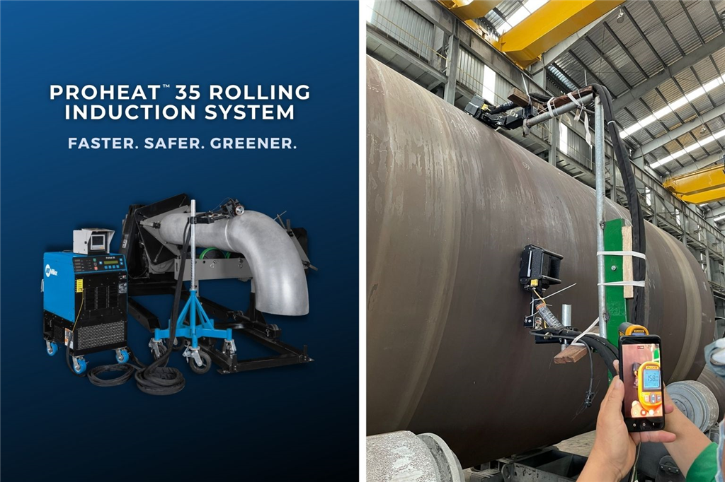
2. Preheating Method. Preheating helps to reduce the cooling rate during welding and drives out moisture, thereby ensuring high-quality welds and reducing the potential for cracking. Most fabricators currently use flame heating to perform preheating of the longitudinal and circumferential joints. Flame heating is very inefficient because a lot of heat is lost to the surrounding, as such, it is not uncommon for fabricators to spend hours just on preheating before welding can take place. In addition, there are safety hazards to consider such as the higher risks of burns and the storage of explosive gases. To improve jobsite safety as well as productivity, some fabricators have switched to induction heating, specifically, the Miller® ProHeat™ 35 Rolling Induction System. These fabricators have experienced a faster time-to-temperature, which means that welders can spend more time welding, instead of waiting.
3. SAW Deposition Rates. Another key factor that will affect welding throughput in monopile fabrication is the welding deposition rate. Because of the thick weld joints, employing a traditional single wire SAW solution will not suffice. For example, a 4.0mm diameter solid wire can only deliver a deposition rate of 8kg/hour at 650A, Direct Current Electrode Positive (DCEP) polarity. A simple way for fabricators to improve deposition rates is to switch to an SAW power sources that offers Variable Balance Squarewave Alternating Current (VBAC), such as the Miller® SubArc AC/DC 1250 Digital. For example, by switching from DCEP polarity to AC polarity, and keeping everything else constant, the deposition rate can be increased by 46% to 11.7kg/hour. If the fabricator decides to change to an AC/AC tandem SAW welding process by adding another welding wire and an additional welding machine, a deposition rate of 25.6kg/hour, or a 220% increase, can be obtained comfortably. Besides changing polarity and the wire configuration, another method to improve deposition rate is to convert the solid wire to a metal-cored wire.
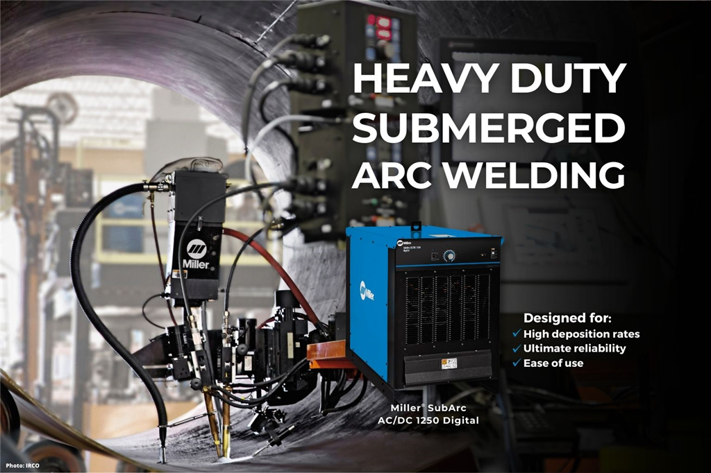
4. Reliability of the SAW Power Source. When purchasing welding machines, besides considering the upfront costs, it is also important to evaluate other factors such as reliability and total cost of ownership. Given the importance of the SAW process in monopile fabrication, companies should invest in proven and reliable welding machine brands, such as Miller®, to minimize any unnecessary downtime that can interrupt the production schedule. The Miller® SubArc AC/DC 1250 Digital is designed based on a reliable thyristor technology, and it delivers 1,000A (44V) at 100% duty cycle. Typically, thyristor machines will last between 15 to 20 years, as compared to 5 to 7 years for inverter machines. Because the Miller® SubArc AC/DC 1250 Digital is a highly reliable power source, contains only one PCB, and has a long-life expectancy, the total cost of ownership may be lower compared to other brands.
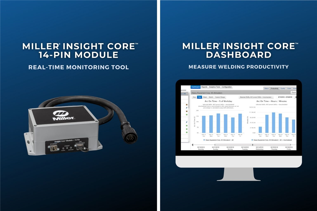
5. Measuring for Success. Before implementing any changes, fabricators should consider measuring each welding station’s arc-on time and establish a productivity baseline. With the latest advancements in welding technology, the collection and analysis of welding data no longer needs to be done manually. For example, the Miller® Insight Core™ is a passive, real-time monitoring tools that can provide visibility into the welding operations so that fabricators can establish a productivity baseline and make plans for improvements. Once changes have been implemented to improve welding productivity, Miller® Insight Core™ can generate reports that help decision makers evaluate the progress towards goals and identify important trends.
Meeting Stringent Mechanical Requirements
Another welding challenge that fabricators may face is meeting the ever-increasing mechanical requirements as monopiles continue to be deployed in deeper waters and harsher environments. What this means for fabricators is that legacy welding procedures and filler metals may no longer meet the mechanical requirements of the latest projects, and fabricators need to source new and improved filler metals from welding suppliers. For example, besides achieving Charpy V-notch impact toughness values at -40oC, certain projects may specify that the filler metal must meet Crack Tip Open Displacement (CTOD) requirements, such as 0.15mm to 0.18mm at -10oC. Experienced filler metal manufacturers, such as Hobart®, work closely with end users to understand the latest trends and requirements. Our Hobart® HN-521 and Hobart® HN-528 fluxes are specially formulated for offshore wind monopile fabrication and will meet both Charpy V-notch impact toughness and the latest CTOD requirements.
In part three of this three-part series, we will elaborate on the welding of another common offshore wind foundation, the jacket foundation.